Visual servo control of a piezoelectric motor
A camera watches a 9 × 6 mm motor, and a PID loop steers it.
A motor the size of a fingernail drifts off course. How do you steer it without adding a single sensor to it?
My master's thesis. The motor is a 9 × 6 mm plate that walks on traveling waves. Left alone it drifts, and any sensor mounted on it would add weight. So a camera watches it instead, and a PID loop corrects it 120 times a second.
github.com/floraliu-dev/piezo-motor-visual-servo ↗ · Python · OpenCV · SCPI · Presented at SPIE Smart Structures 2026
The motor
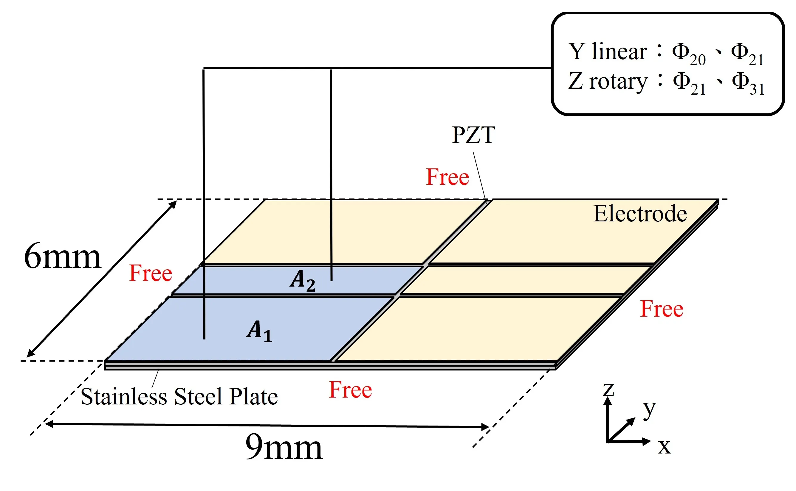
A PZT sheet on a stainless steel plate, both 9 × 6 mm, free on every edge. Exciting two vibration modes together, out of phase, turns standing waves into a traveling wave that pushes the plate along. One pair of modes moves it in a straight line; another pair turns it on the spot. The electrode layout decides how strongly each mode is driven.
Closing the loop with a camera
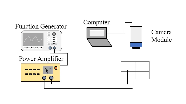
A camera adds no weight and touches nothing, and it sees both position and heading at once. A global-shutter camera above the motor feeds a computer; the computer sets the function generator, whose signal a power amplifier raises to drive the motor.
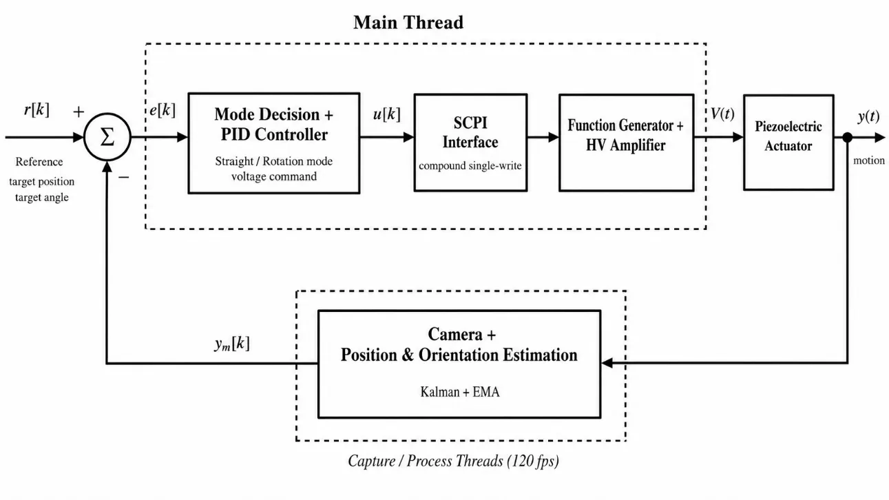
Each frame, the software finds the motor, filters its position and heading, compares them with the target, and turns the error into a drive command. Capture, image processing and control run on separate threads so they overlap.
- Feedback rate
- 120.6 FPS
- Camera to command
- 12.4 ms
- Dropped frames
- 0 of 2,500
- Calibration error
- 0.094 mm
Does the control work?
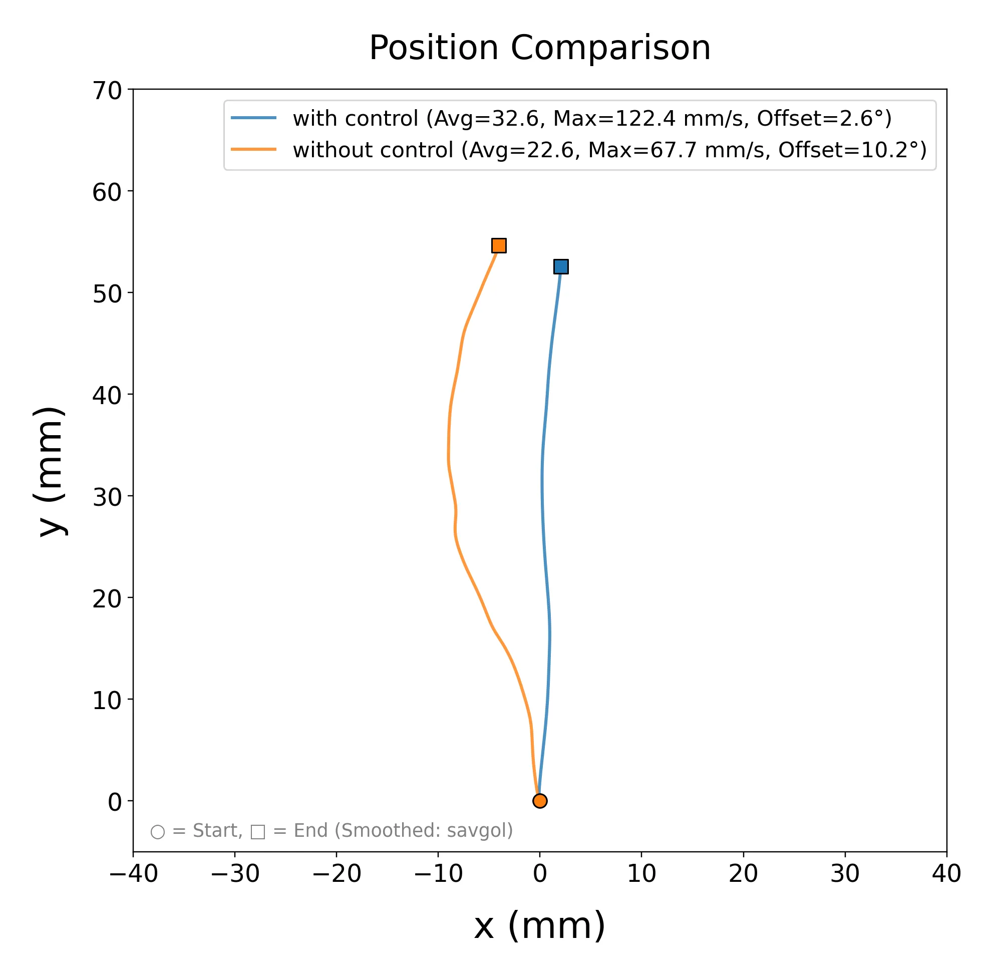
Driving straight, the uncontrolled motor wanders off line. With heading control it holds its course, and it is faster too: top speed rises from 67.7 to 122.4 mm/s.
Turning on the spot to a target angle between 3° and 8°, it settles within about 1.2° of the target.
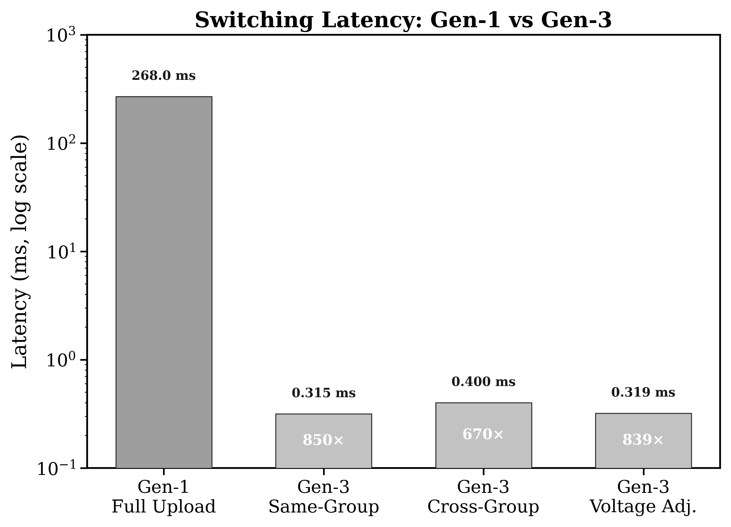
Switching drive modes in under a millisecond
Changing direction first meant re-uploading the waveform: about 268 ms, some 30 frames with no new command. Preloading the waveforms and sending every change as one compound SCPI command brought it under a millisecond, more than 600 times faster.
Try it
-
Run from source:
pip install -r requirements.txt, thenpython main.py. Camera, mode and instrument address are set inconfig.py. - Every run saves a tracked video, a raw video, a CSV and plots.
- Full latency and throughput benchmarks ↗